
Cart 2 india
In2Cart
Rs. 0
0


Product Information
Specification
Brand : YOUTHINK
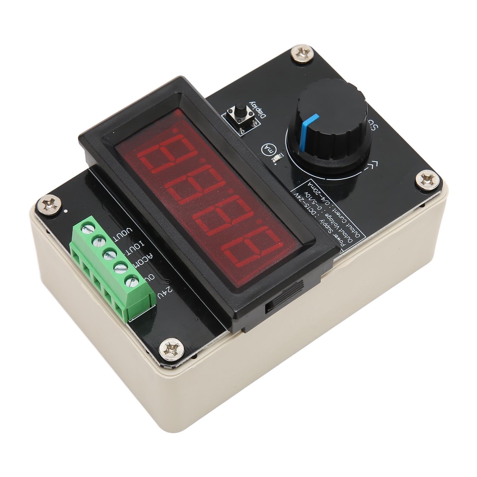
BulletPoint1 : [Versatile Use] Suitable for signal generators, plc commissioning, led testing and more, offering a wide range of applications.
BulletPoint2 : [Bright LED Display] Features a clear three-digit LED display for easy monitoring of output current and voltage.
BulletPoint3 : [Exact main function] This signal generator produces 0/4 to 20ma current signal and 0 to 10v voltage signal, ideal for valve control.
BulletPoint4 : [Accurate Readings] LED display shows current accuracy to 0.1ma and voltage accuracy to 0.01v, ensuring results.
BulletPoint5 : [Precise Calibration] Calibration potentiometers with current and voltage displays enable accurate adjustments.
Color : As Shown
ExternallyAssignedProductIdentifier : 6131323817588
IncludedComponents : No
ItemName : Signal Generator, 4 to 20mA Adjustable DC 0 to 10V 0 Or 4 to 20mA Current Voltage Analog Simulator for Valve Regulation Inverter Control PLC Commissioning
ItemPackageDimensions_Height : 6 centimeters
ItemPackageDimensions_Length : 12 centimeters
ItemPackageDimensions_Width : 9 centimeters
ItemPackageQuantity : 1
ItemTypeKeyword : function-generators
Manufacturer : YOUTHINK
MeasurementAccuracy : 0.1mm
ModelName : YOUTHINK56tnxf03w1
ModelNumber : YOUTHINK56tnxf03w1
NumberOfItems : 1
PartNumber : YOUTHINK56tnxf03w1
ProductDescription : Spec:
Item Type: Signal Generator
Material: ABS
Working Voltage: DC24V
Input Signal: Potentiometer
Output Signal : 0/4- 20mA or 0-10V
Package List:
1 x
Signal Generator
How To Use:
1 Switch voltage/current mode: click Display to switch current voltage/current mode, digital the current output value, encoder to change the output value, encoder reset, reset the output value;
2 Enter the menu mode method: Long press the encoder , the screen appears and then the encoder every rotation down; In voltage mode, the sequence is right left left, the screen will show rLLr and the correct password will automatically enter the menu screen and show Poo
Note:
A; Current display correction Set the multicycle potentiometers to maximum clockwise, switch the display to the right and test the current output value with the multimeter's current stop. Adjust the current display to adjust the potentiometer so that the display corresponds to the actual current output value
B; Correction of voltage display The multicycle potentiometer is adjusted to the maximum clockwise, the display switch is set to the left, and the voltage on the multimeter is used to test the actual output voltage value. At this time, the voltage display is adjusted to adjust the potentiometer so that the display corresponds to the actual voltage output value
ProductSiteLaunchDate : 2024-08-26T07:47:51.376Z
Size : 100x60mm
SupplierDeclaredDgHzRegulation : not_applicable
UnitCount : 2.1164
UnspscCode : 40141600